|
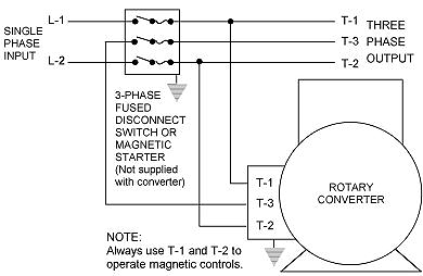
Rotary
Converter Installation Instructions
|
..
1.
|
.
Magnetic controls or single-phase
loads must always be energized by
lines T-1 and T-2. Never connect a ground
or neutral to line T-3 (Mfg. phase), which can easily
be identified as the line with the highest voltage
to ground with the converter running.
|
| 2. |
It
is essential that careful consideration
be given to your wiring
length and size to prevent
slow starting due to a voltage
drop . Consult National Electrical
Code for proper wire sizing.
|
| 3. |
When
starting a motor of the same horsepower
as the " Largest Motor" rating of the rotary
converter, some drop in starting torque may
occur in heavily loaded applications due to
the higher starting current. However,
full running torque is usually still obtained. Refer
to APPLICATION NOTES
for sizing considerations.
|
| 4. |
The
tables below show the appropriate idle current
at the specified voltage. Higher line voltage will
cause idle current to increase. Excessive amperage
could also be caused by incorrect installation.
|
| 5. |
Properly
ground all electrical equipment. |
| 6. |
Converter
should reach full speed within 2 to 3 seconds.
|
| 7. |
Lubricate every 12 months for normal operation,
or every 6 months for continuous (24 hour) operation.
Use high temp bearing grease,
(Shell "Dolium R" or equivalent)
available from GROMAX.
|
| 8. |
Converters are intended for use
in clean, dry locations with
access to an adequate supply of cooling
air. In addition, there should
be protection from or avoidance of flammable
or combustible materials in the
area of converters as they can eject flame
and/or metal in the event of an insulation failure.
|
220V
|
230V Models ( R Series) & Electrical Specifications
|
|
Model
|
Largest
Motor HP See *Note Below
|
Total
Combined HP Load See **Note Below
|
Approx.
Idle Current
|
Disconnect Switch Fuse (Time Delay)
|
NEMA
Starter
|
Starter
Heater
|
Minimum
Single Phase Supply
See ***Note Below
|
| R-1 |
1 HP*
|
3 HP**
|
1.5 AMPS
|
10 AMPS
|
00
|
4.8 AMPS
|
15 AMPS***
|
| R-2 |
2 HP*
|
6 HP**
|
2 AMPS
|
10 AMPS
|
0
|
7.7 A
|
15 AMPS***
|
| R-3 |
3 HP*
|
9 HP**
|
2.5 AMPS
|
15 AMPS
|
0
|
10.4 A
|
20 AMPS***
|
| R-5 |
5 HP*
|
15 HP**
|
3 AMPS
|
30 AMPS
|
1
|
15.9 A
|
30 AMPS***
|
| R-7 |
7 1/2 HP*
|
22 HP**
|
5 AMPS
|
40 AMPS
|
1
|
26 A
|
40 AMPS***
|
| R-10 |
10 HP*
|
30 HP**
|
7 AMPS
|
45 AMPS
|
2
|
35 A
|
60 AMPS***
|
| R-15 |
15 HP*
|
45 HP**
|
8 AMPS
|
60 AMPS
|
3
|
48 A
|
100 AMPS***
|
| R-20 |
20 HP*
|
60 HP**
|
10 AMPS
|
80 AMPS
|
3
|
63 A
|
125 AMPS***
|
| R-25 |
25 HP*
|
75 HP**
|
11 AMPS
|
100 AMPS
|
3
|
80 A
|
160 AMPS***
|
| R-30 |
30 HP*
|
90 HP**
|
12 AMPS
|
125 AMPS
|
3
|
94 A
|
200 AMPS***
|
| R-40 |
40 HP*
|
120 HP**
|
13 AMPS
|
150 AMPS
|
4
|
117 A
|
250 AMPS***
|
| R-50 |
50 HP*
|
150 HP**
|
15 AMPS
|
200 AMPS
|
5
|
145 A
|
300 AMPS***
|
| *Largest Motor HP: Almost
all machines require sizing the converter 50%
larger or more than the largest HP motor
of your machine.
**Total Combined HP Load:
HP shown in chart reflects
maximum HP allowable under specific conditions.
EXAMPLE: Multiple machinery not started
at the same time and that is running lightly
loaded.
***Minimum Single
Phase Supply: Single-phase supply shown is for absolute maximum
output of the Rotary Converter. Most of the
time the converter is oversized to provide
the high starting current for the motor. It
is not always necessary to use single-phase
breakers sized this large. See the following
formula.
Formula: Total three-phase amperage
(running load amperage) the machine(s) will
ever draw multiplied by 1.5 (extra single-phase
needed to generate the third leg), then add
the idle current of the Rotary Converter.
That will give you the total single-phase
amps that will ever be drawn from the single-phase
lines. Size the single-phase breaker minimum
20% above that total amperage draw and size
the wire accordingly.
IMPORTANT: This chart is simplified and cannot reflect
the many types of applications possible. Contact
GROMAX to verify your phase converter requirements.
Also refer to APPLICATION NOTES for sizing considerations.
Larger
Horsepower phase converter systems may
be obtained by connecting multiple Rotary
Converters in parallel. See Multiple Units Banked Together.
|
|
460V
|
460V Models ( RH Series) & Electrical Specifications
|
| Model |
Largest
Motor
HP
See *Note Below |
Total
Combined
HP Load See **Note Below |
Approx.
Idle
Current |
Disconnect
Switch Fuse
(Time Delay) |
NEMA
Starter |
Starter Heater |
Minimum Single Phase Supply
See
***Note Below |
| RH-20 |
20 HP* |
60 HP** |
5 AMPS |
40 AMPS |
2 |
35 AMPS |
60 AMPS*** |
| RH-30 |
30 HP* |
90 HP** |
6 AMPS
|
60 AMPS |
3 |
48 AMPS |
100 AMPS*** |
| RH-40 |
40 HP* |
120 HP** |
8 AMPS |
80 AMPS |
3 |
63 AMPS |
125 AMPS*** |
| RH-50 |
50 HP* |
150 HP** |
9 AMPS |
100 AMPS |
3 |
78 AMPS |
150 AMPS*** |
| *Largest Motor HP: Almost
all machines require sizing the converter 50%
larger or more than the largest HP motor
of your machine.
**Total Combined HP Load:
HP shown in chart reflects
maximum HP allowable under specific conditions.
EXAMPLE: Multiple machinery not started
at the same time and that is running lightly
loaded.
***Minimum Single
Phase Supply: Single-phase supply shown is for absolute maximum
output of the Rotary Converter. Most of the
time the converter is oversized to provide
the high starting current for the motor. It
is not always necessary to use single-phase
breakers sized this large. See the following
formula.
Formula: Total three-phase amperage
(running load amperage) the machine(s) will
ever draw multiplied by 1.5 (extra single-phase
needed to generate the third leg), then add
the idle current of the Rotary Converter.
That will give you the total single-phase
amps that will ever be drawn from the single-phase
lines. Size the single-phase breaker minimum
20% above that total amperage draw and size
the wire accordingly.
IMPORTANT: This chart is simplified and cannot reflect
the many types of applications possible. Contact
GROMAX to verify your phase converter requirements.
Also refer to APPLICATION NOTES for sizing considerations.
Larger
Horsepower phase converter systems may
be obtained by connecting multiple Rotary
Converters in parallel. See Multiple Units Banked Together.
|
|
Single Unit Installation
Illustration
|
R
Series is 208-230V single-phase in
and 208-230V three-phase out.
RH Series is 460V single-phase
in and 460V three-phase out.
Higher line voltages or voltage sensitive applications,
such as CNC equipment, may require a Voltage Stabilizer.
If
you have single-phase that is 208-230V and you need
460V three-phase out, or visa-versa, a transformer
can be used to step the voltages up or down as required.
Consult factory.
|
XX
 |
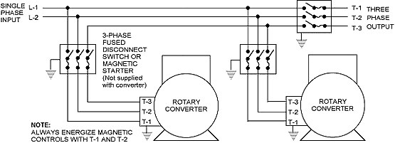
Multiple Unit Installation Illustration
Multiple Units Banked Together
.
R Series is 208-230V single-phase in
and 208-230V three-phase out.
RH Series is 460V single-phase
in and 460V three-phase out.
Higher line voltages or voltage sensitive applications,
such as CNC equipment, may require a Voltage Stabilizer.
If you have single-phase that is
208-230V and you need 460V three-phase out,
or visa-versa, a transformer can be used to
step the voltages up or down as required. Consult
factory. |
|
|
XX

|
Multiple Unit Installation
Instructions
| A. |
1,000
HP or more is possible by connecting multiple units
together in banks as required. Potential output is
limited only by adequate wiring size and your single-phase
supply available. Consult factory for these options.
|
| B. |
Caution: Special care must be taken to connect all
T-1 lines and all T-2 lines together. Test run the
individual units before connecting the T-3 lines together.
Carefully measure the voltages between the different
T-3 lines. It should not read more than 60V for the
R Series, and 110V for the RH Series, but could read
much less. This will ensure that you have proper phase
rotation. Cross phasing will cause a dead short and
possible damage.
|
| C. |
Fuses
or magnetic starters should be sized for the individual
converters and not for the total load.
|
| D. |
The
converters may be started either individually to reduce
line surge, or may be started simultaneously depending
on the limitations of your single phase supply available.
|
|