|
|
||||||||||||||||||
|
COMPANY
INFO
| MAP Last
Updated: 9/22/2005 • PRICES, SPECIFICATIONS, AND FEATURES SUBJECT TO CHANGE WITHOUT NOTICE.
|
The HydroFLOW Patented Technology - a unique and new approach to physical water treatment The most important feature of the HydroFLOW technology that sets it apart from that of any competing technology, is the efficient manner by which the electric field is directionally generated through the entire water system. This unique advantage, protected by international patents, singularly delivers consistently beneficial results in industrial, commercial, and domestic applications.
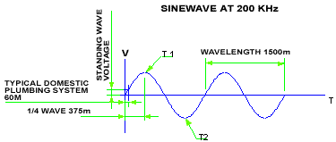
Fig.2 represents the position at T1 on Fig.1 and Fig. 3 represent the position at T2 on Fig.1. To achieve this flow of electrons in the plumbing system a voltage must be generated in the water in the direction of the pipe. This is achieved by utilising a high frequency transformer. This transformer consists of a ferrite ring around the water pipe. A primary coil is wound around the ferrite ring. Any conductor, the water and the pipe (if it is a conductive material) will form parallel secondary windings of the transformer. The signal that is fed to the primary coil is a high frequency diminishing wave with random wait periods. This wave is designed to allow the formation of seed crystals for a variety of crystal forming salts that may be present in the water. Fig.2 and Fig.3 illustrate the diminishing wave and the voltage V over the plumbing system at specific times marked T1 and T2 in Fig.1, as well as the position of the electrons, and the positively charged atoms in the conducting water (and pipe), at maximum voltage position. V is the voltage generated by the ferrite ring and, I is the accelerated charge generated due to the standing wave. It is this acceleration that forms the electromagnetic field. The electric component is responsible for the generation of nuclear clusters that act as seed crystals to prevent the formation of encrusting scale. |
||||||||||||||||||||||||


